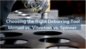
Choosing the Right Metal Deburring Tools – Manual vs. Vibration vs. Spinner | A Complete Guide
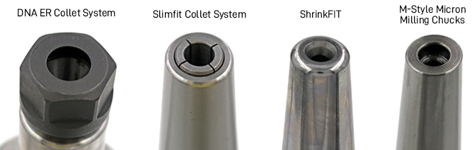
The combination of TTG and Eppinger offers our customers a convenient single source for the highest quality tooling solutions for CNC mills, lathes, and routers.

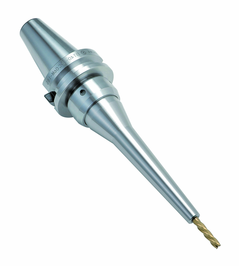
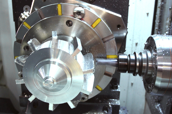
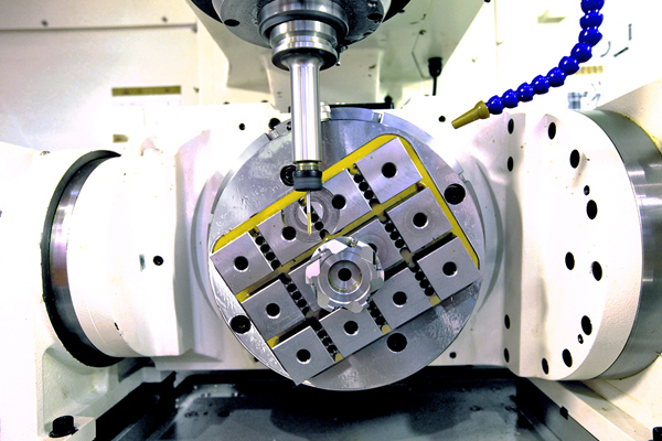
What is a turbo turn and how does it work in CNC tooling?
What is Parlec’s Turbo-Turn Parlec understands that manufacturers increasingly require customized tooling solutions to meet

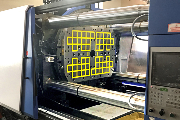
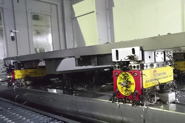
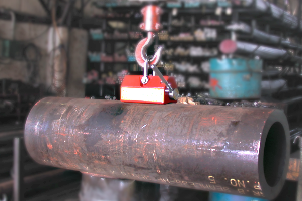
Benefits of Using Lifting Magnets
Benefits of Using Lifting Magnets Lifting magnets offer a range of advantages in a variety

Techniks Tool Group announces the acquisition of ESA Eppinger GmbH and EXSYS Automation
The combination of TTG and Eppinger offers our customers a convenient single source for the highest quality tooling solutions for CNC mills, lathes, and routers.
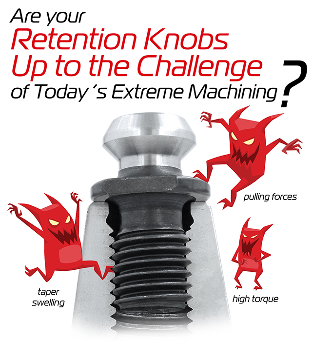
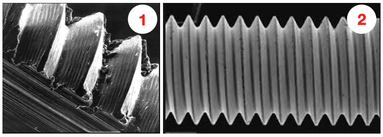
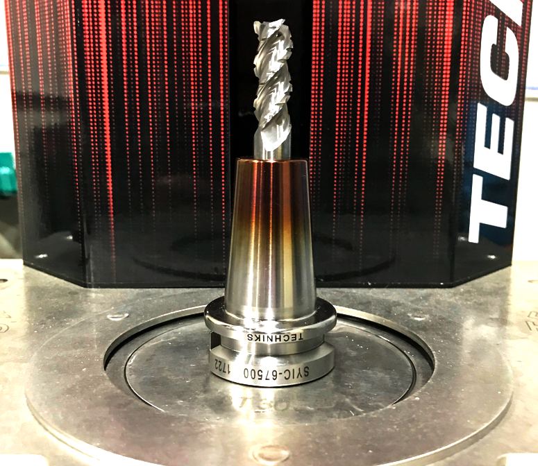
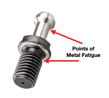 Pull studs encounter catastrophic failure as a result of metal fatigue caused by a number of reasons including: poor choice of base material, engineering design, machining process, poor heat treatment, and, sometimes, they have just met or exceeded their service life. Also, the repetitive loading and unloading cycles that the retention knob goes through is a significant source of stress that can cause fatigue and cracking at weak areas of the pull stud.
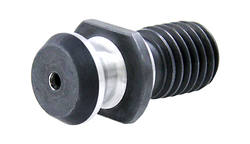
The most common failure points for a retention knob is at the top of the first thread, and the underside of the pull stud where the grippers or ball bearings of the drawbar engage and draw the toolholder into the spindle.
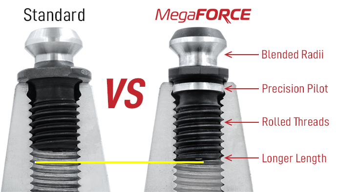
For the same reason we put corner radiuses on end mills, sharp corners are a common area of failure for any mechanical device. The same holds true with your pull studs: The sharp angles on the head of the retention knob and at the minor diameter of the threads are common locations of catastrophic material failure.
Remember, bigger Radii are stronger than sharp corners.