Recent Posts

Choosing the Right Metal Deburring Tools – Manual vs. Vibration vs. Spinner | A Complete Guide
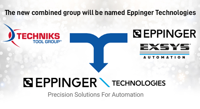
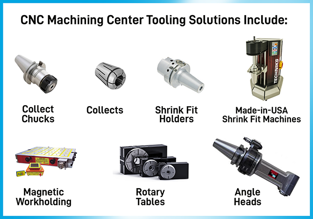
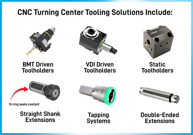
The combination of TTG and Eppinger offers our customers a convenient single source for the highest quality tooling solutions for CNC mills, lathes, and routers.
What is a turbo turn and how does it work in CNC tooling?
What is Parlec’s Turbo-Turn Parlec understands that manufacturers increasingly require customized tooling solutions to meet

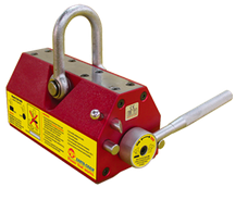
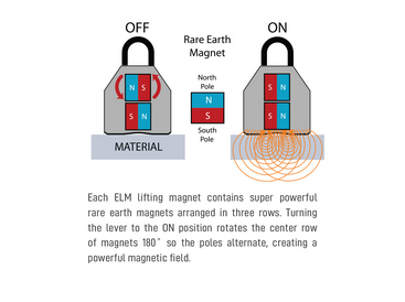
Benefits of Using Lifting Magnets
Benefits of Using Lifting Magnets Lifting magnets offer a range of advantages in a variety
Techniks Tool Group announces the acquisition of ESA Eppinger GmbH and EXSYS Automation
The combination of TTG and Eppinger offers our customers a convenient single source for the highest quality tooling solutions for CNC mills, lathes, and routers.
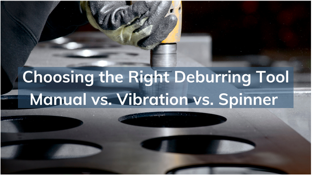
Choosing the Right Metal Deburring Tools - Manual vs. Vibration vs. Spinner | A Complete Guide
Over the years, metal deburring tools have stirred the manufacturing and CNC machining world with their sheer capability.
The Global Deburring tools market is likely to grow at a CAGR of 4.4% between 2021 and 2027. (Digital journal).
Here’s why:
In the world of manufacturing and CNC machining, precision and perfection are paramount. Every step of the production process is carefully executed to ensure that the end products meet the highest standards.
But the reality is that even with the most advanced machining techniques, rough edges and burrs can be left behind on the machined parts. These burrs not only compromise the quality of the components, but also pose a threat to the overall performance and safety.
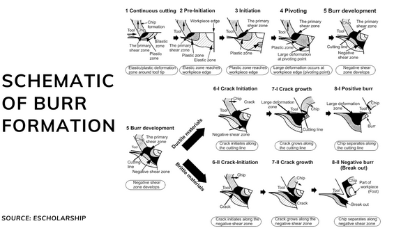
Here’s an image that shows the 8 different stages of burr formation. Stages 1-5 show crack-free burr development, while stages 6-8 explain crack-induced chip separation. (Escholarship)
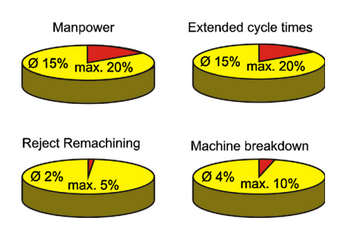
In fact: a study by CIRP found that burrs on machined parts led to 2% of the reject rate and a 4% of machine breakdown times. In addition, burrs also led to a 15% increase in the manpower expenses and a 15% longer cycle time.
Source: escholarship.org
And that’s not all:
OSHA (Occupational Safety and Health Administration) regulations also stipulate the removal of burrs to guarantee worker safety within the manufacturing environment.
This is where deburring tools for metal come into play. With the ability to ensure superior product quality, reduce manufacturing costs and adherence to safety compliance, metal deburring tools are a revelation for the manufacturing and CNC machining fraternity.
In fact, the CIRP study further indicates that deburring significantly diminishes the likelihood of product failure and considerably extends the lifespan of the workpiece.
By using efficient metal deburring tools, manufacturers can not only enhance product quality and reliability but also optimize their financial resources. In this guide, we will explore the different types of deburring tools for metal, their advantages, and disadvantages, and how to choose the right one for your needs.
Introduction to Metal Deburring Tools
Metal Deburring tools are used to remove burrs, which are raised edges or small pieces of material that are left on metal parts after machining. These burrs can cause problems such as poor surface finish, reduced part functionality, and even injury to the operator. Tools for deburring can be manual or automated; and they come in various shapes and sizes, depending on the application.
Many innovative metal deburring tools have emerged to cater to the diverse needs of the machining industry. Manufacturers are on a constant lookout to embrace a suitable Metal deburring tool to optimize their operations, enhance customer satisfaction, and stay competitive in today’s dynamic marketplace.
However, choosing the right metal deburring tool can be a daunting task, as there are several options available, including manual, vibration, and spinner deburring tools.
Importance of Choosing the Right Deburring Tools for Metal
In the world of metalworking, the importance of selecting the appropriate metal deburring tool cannot be overstated. Achieving the desired results and maintaining the utmost precision relies heavily on this critical decision.
Remember, each deburring tool for metal comes with its unique features, catering to specific applications. From manual tools that offer intricate control to automated solutions for high-volume tasks, the diversity of options can be overwhelming.
As manufacturers and CNC machinists, it is crucial to conduct a thorough analysis of the deburring requirements for each project and select the appropriate tool accordingly. Opting for the wrong tool can spell disaster, potentially damaging the workpiece or leaving it with an unsatisfactory and uneven surface finish, which in turn can significantly impact the part’s functionality. Such outcomes can be detrimental to a project’s success, resulting in costly rework and wasted time.
A lot of machinists find it really daunting to select the right deburring tool for metal. Resultantly, they often end up with damaged parts, uneven surface finishes, compromised functionality, costly rework, and extended production timelines.
To ensure utmost efficiency, productivity, and cost-effectiveness, it is important to carefully consider various factors when choosing the ideal metal deburring tool. Let’s delve into these crucial aspects and their impact on the deburring process:
Factors to Consider While Choosing the Right Metal Deburring Tool:
1. Material: The type of material being deburred is a fundamental factor to consider when it comes to selecting the best metal deburring tool. Materials such as aluminum, steel, or composites require specific deburring tools for metal. For instance, magnetic deburring tools prove to be highly effective for ferrous metals, while manual deburring tools may be more suitable for softer materials like plastics or brass.
2. Size and Shape: The size and shape of the parts being deburred significantly influence the choice of tools. For small parts, intricate manual deburring tools offer precise control. Conversely, larger parts may demand automated tools, such as vibration deburring tools or sPINner Magnetic Deburring, which can handle higher volumes and reach tight spaces.
3. Deburring Method: The deburring method chosen also impacts the selection of the deburring tool for metal. For simple shapes and small quantities, manual deburring is a cost-effective choice, while automated methods, like vibratory or spinner deburring, excel in handling large volumes and complex shapes.
4. Cost: Cost considerations are vital in any manufacturing decision. Manual deburring tools generally come with lower upfront costs, making them appealing for smaller operations. However, when analyzing the long-term picture, automated solutions may prove more cost-effective due to their increased efficiency and reduced labor requirements. Investing in an automated deburring machine, like a spinner deburring tool, can lead to significant savings over time.
5. Safety: Prioritizing operator safety is a non-negotiable aspect when choosing the right metal deburring tool. Some methods, such as manual deburring or using vibratory deburring tools, may require additional safety measures and precautions due to their direct operator involvement. Automated methods, on the other hand, reduce operator exposure to potential hazards, thereby enhancing workplace safety and efficiency.
By making informed decisions and investing in suitable metal deburring tools, businesses can achieve superior results, reduce production timelines, and elevate their competitive edge in the industry.
Manual Deburring Vs Vibratory Deburring Vs sPINner Deburring Tools
When it comes to selecting the perfect deburring tool for metal, there are three clear contenders – manual deburr tools, vibratory deburring tools, and spinner deburring tools. These three stalwarts offer a range of capabilities to bring out the best in all machining endeavors.
Here’s a quick comparison to help you make an informed decision:
| Deburring Tool | Process | Application | Efficiency | Suitability for Complex Shapes | Cost |
|---|---|---|---|---|---|
|
Manual Deburring Tool |
-Manual removal of burrs and sharp edges using hand tools |
-Suitable for small parts and simple shapes |
-Moderate
-Requires more time and effort
|
-Limited.
-Not very effective for larger volumes or complex shapes
|
-Affordable upfront but labor-intensive and costly in terms of operational expenses and maintenance costs |
|
Vibratory Deburring Tool |
-Automated process using vibration and abrasive media |
-Can handle larger volumes and more complex shapes |
-High
-Consistent results through a controlled process
|
-Better than manual, but not as efficient as spinner deburring |
-Moderate to high, depending on machine size and features |
|
sPINner Deburring Tool |
-Automated process using stainless steel media excited in a magnetic field |
-Efficient for large volumes of small and complex shapes |
-Very high
-Achieves desired results quickly and effectively
|
-Highly effective for complex shapes |
-Moderate initial investment, but cost-efficient for high-volume production. |
When comparing Manual Deburring, Vibratory Deburring, and Spinner Deburring Tools for Metal, it becomes evident that each type offers unique advantages and is suitable for specific applications.
Manual Deburring tools are simple, cost-effective solutions for small-scale operations, but they may prove time-consuming and labor-intensive for larger production volumes or intricate shapes. Extra investments including overhead expenses and workers’ safety risks make these tools a costly alternative.
Vibratory Deburring tools, on the other hand, offer automation and consistent results, making them more suitable for handling larger quantities and complex parts compared to manual tools. However, when efficiency and speed are of the essence, magnetic spinner deburring tools for metal stand out as the superior option.
Unsurprisingly, magnetic spinner deburring tools remain the obvious choice for industries seeking to scale their deburring efficiency, boost precision and control, and minimize the risk of damaging delicate workpieces.
Magnetic sPINner Deburring Tool – The Ultimate Solution?
The emergence of magnetic deburring technology is a game-changer in the world of metalworking. Increased precision and efficiency achieved through these magnetic deburring tools is revolutionizing the way burrs and imperfections are tackled, positioning them as a compelling option for manufacturers seeking unparalleled performance.
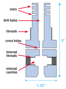
Precision at its Core: Spinner deburring tools epitomize precision with the integration of magnetic technology. Small stainless steel pins media is excited in a magnetic field creating a ‘form-fitting’ brushing effect, allowing for consistent deburring of even the most intricate shapes and contours. This level of precision minimizes the risk of damage to delicate parts while achieving flawless results.
Unparalleled Efficiency: Time is of the essence in modern manufacturing, and magnetic spinner deburring tools for metal embrace the need for speed. Leveraging the power of the small stainless steel pin media, these machines efficiently and rapidly remove burrs from a multitude of parts simultaneously. Since the media is propelled via the rapidly rotating magnetic, it retains its energy even in the I.D. area of parts ensuring a thorough and consistent deburring process, significantly reducing overall production time and elevating productivity to new heights.
Gentle Touch, Maximum Impact: One of the most significant benefits of using lifting magnets is its gentle touch on the workpiece. The gentle brushing action of the stainless steel media on the workpieces does not cause any distortion or stress, even for sensitive or fragile materials. This gentle approach, combined with the precision deburring, contributes to enhancing the overall part quality and functionality.
Customized Solutions: Manufacturers and CNC machinists can enjoy the flexibility and adaptability offered by sPINner deburring machines. These tools can be tailored to specific needs, accommodating various part sizes, shapes, and materials. The versatility ensures that magnetic deburring technology can seamlessly integrate into existing production lines, enhancing the overall efficiency and versatility of the manufacturing process.
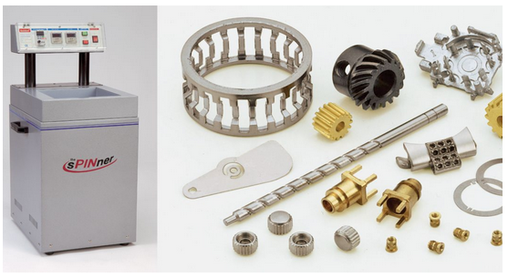
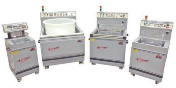
Techniks sPINner Deburring Machines – A Step Above the Rest
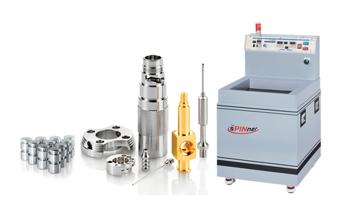
At Techniks, we take pride in offering state-of-art deburring solutions with our sPINner deburring machines. Engineered to deliver exceptional results, our machines are built to withstand rigorous manufacturing environments while ensuring top-notch precision and efficiency.
Experience the power of Techniks sPINner Deburring Machines and elevate your metalworking endeavors to new heights of excellence.
Techniks sPINner Deburring Machine – Key Features:
- Unmatched Finish Quality: Techniks sPINner Deburring Machine offers a flawless finish that surpasses expectations, all thanks to the magnetized 304 steel pin media used in these amazing metal deburring tools.
- Precision in Reach: Our magnetic deburring machine effortlessly accesses areas where hand deburring can’t reach eliminating the limitations of manual deburring methods.
- Irregular and Precision Parts: From irregular parts to small precision components, Techniks magnetic deburring machine offers flawless results, no matter the complexity.
Techniks Magnetic Spinner Deburring Machine – Key Benefits:
- Speed and Precision: It offers fast and efficient deburring without compromising part integrity or affecting tolerances.
- Long-Lasting Performance:The sPINner media boasts an impressive lifespan of 3-5 years, ensuring durability and cost-effectiveness for your operations.
- Streamlined Production: For high-volume needs, there is a parts separator available, that further optimizes your manufacturing process.
- Preserve Part Integrity: Rest assured that Techniks Magnetic Deburring Machines do not transfer materials or introduce new particles, preserving the integrity of your parts.
Techniks Magnetic Spinner Deburring Machine – Case Examples
Let’s now discover the impressive capabilities of Techniks Magnetic Deburring Machines through three illustrative case examples. These real-world scenarios demonstrate the efficiency and precision of these machines in tackling various deburring challenges encountered in metalworking applications.
Case Example 1 – Aluminum Gears
| Dimensions | Problem | Deburring Time |
|---|---|---|
|
1 9/16″ diameter x 5/16″ high
|
Soft material, irregular shape with burrs left in multiple gear gaps and rough edges.
|
10 minutes
|
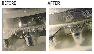
In this case, we encounter aluminum gears with dimensions of 1 9/16″ in diameter and 5/16″ in height. The material’s softness and irregular shape present a unique deburring challenge, leading to burrs left in multiple gear gaps and rough edges after machining. The goal is to achieve a flawless finish while ensuring smooth gear operation. With the aid of Techniks Magnetic Deburring Machine, this task is completed efficiently in just 10 minutes, enhancing the overall quality and functionality of the gears.
Case Example 2 – Aluminum Cooling Fins
| Dimensions | Problem | Deburring Time |
|---|---|---|
|
4.75″ x 2.125″ x 2.75″
|
Soft material with long burrs left in multiple thin slits and rough edges.
|
15 minutes
|
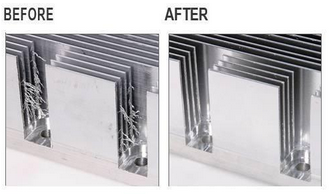
This case revolves around aluminum cooling fins with dimensions measuring 4.75″ in length, 2.125″ in width, and 2.75″ in height. The softness of the material poses a deburring challenge, particularly due to long burrs left in multiple thin slits and rough edges. Proper deburring is crucial to ensure optimal heat dissipation and efficient cooling fin performance. The Techniks Magnetic Deburring Machine proves its worth in this scenario, accomplishing the deburring process effectively in 15 minutes, resulting in cooling fins that meet the highest quality standards.
Case Example 3 – Stainless Steel Turned & Machined Part
| Dimensions | Problem | Deburring Time |
|---|---|---|
|
3/4″ diameter x 1 7/16″ long
|
Rusty compact cylinder with burrs left in multiple cross-drilled holes.
|
20 minutes |
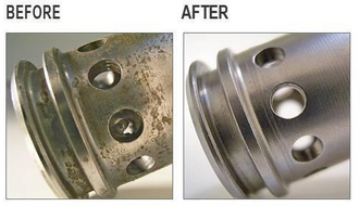
In this case, we encounter a stainless steel turned and machined part with dimensions of 3/4″ in diameter and 1 7/16″ in length. The part exhibits a rusty compact cylinder with burrs persisting in multiple cross-drilled holes. The challenge lies in achieving a smooth and corrosion-resistant surface while ensuring burrs are completely removed from the intricate cross-drilled holes. The Techniks Magnetic Deburring Machine showcases its capabilities by successfully tackling this task in 20 minutes, delivering a top-quality, pristine finish to the stainless-steel part.
These three case examples showcase the versatility and efficiency of Techniks SPINner Machines as an effective metal deburring tool in addressing various deburring challenges encountered in metalworking.
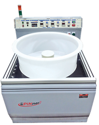
How Magnetic Spinner Deburring Machine Works?
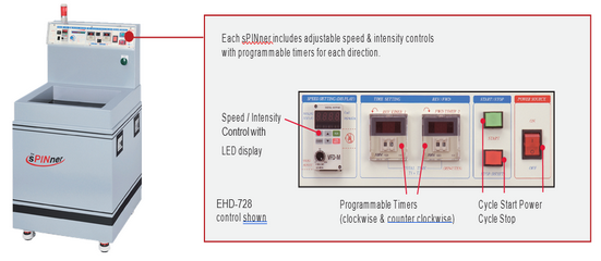
Operating the Magnetic Spinner Deburring Machine is a seamless process with its intuitive controls and customizable features. The Spinner Operation Guide equips you with adjustable speed and intensity controls, along with programmable timers for each direction, granting you complete control over the deburring process. The LED display ensures precision and delivers customized results.
The Magnetic Spinner’s functionality relies on powerful magnets situated below the sPINner well, creating a rotating magnetic field within the sPINner tub. This stirring action, when paired with magnetized stainless steel pin media, effectively deburrs, smooths rough edges, and polishes your parts, resulting in the best possible finish.
Here are a few usage tips to operate the Magnetic Deburring Machine:
- When working with hard materials that require more power, choose media with a diameter of 0.5mm or larger.
- For softer materials, use media with a diameter of 0.5mm or smaller.
- When dealing with parts that have small holes and crevices, opt for 3mm length media.
- Always make sure that the diameter of the media is smaller than the holes present in your parts.
By following the recommended operation procedure and usage tips, you can effortlessly achieve optimal results, ensuring your parts undergo a thorough and efficient deburring process.
Magnetic Spinner Deburring Tool for Metal Maintenance and Safety Tips
Proper maintenance and safety are crucial for the effective and safe use of metal deburring power tools. Regular maintenance can prolong the life of the tool and ensure that it operates correctly. It is essential to follow the manufacturer’s instructions for maintenance and to inspect the tool regularly for any signs of wear or damage.
Safety is critical when using deburring tools for metal. One should never use a tool that is damaged or malfunctioning. Operators should wear appropriate personal protective equipment, such as gloves and safety glasses, and should be trained in the safe use of the tool holders. It is also essential to adhere to the manufacturer’s recommendations and follow all safety guidelines while using a metal deburring tool.
Conclusion
Choosing the right metal deburring tool is essential for the health of your machining parts and accessories. Manual, vibration, and sPINner deburring tools for metal are all effective methods for removing burrs and sharp edges from metal parts, but each has its advantages and disadvantages. When selecting a metal deburring tool, it is essential to consider the material being deburred, the size and shape of the part, the deburring method, and your budget. Magnetic deburring tools provide the most efficient, precise, and cost effective results to large volume manufacturing units that want to stay ahead of the competition. Having reliable components is crucial across various industries, but it holds even greater significance for sectors dealing with high-value products like automotive, medical aerospace, and defense industries, where achieving top-notch quality is imperative. As an industry leader, Techniks prides itself in providing specialized solutions, such as the SPINner Deburring machine, to cater to the growing needs of metal deburring tools in the metalworking market.

Greg Webb
Greg has been with Techniks Tool Group for over 23 years serving in many roles from VP of Sales to President & CEO during which he has gained a deep understanding of CNC manufacturing processes and how to optimize tooling and workholding solutions for specific applications. He has written several articles, white papers, and blogs on various tooling, deburring, and workholding-related topics. As a recognized subject matter expert on CNC tooling, Greg is often approached to provide opinions and content for technical articles.
- Categories: Tech Tips Blog