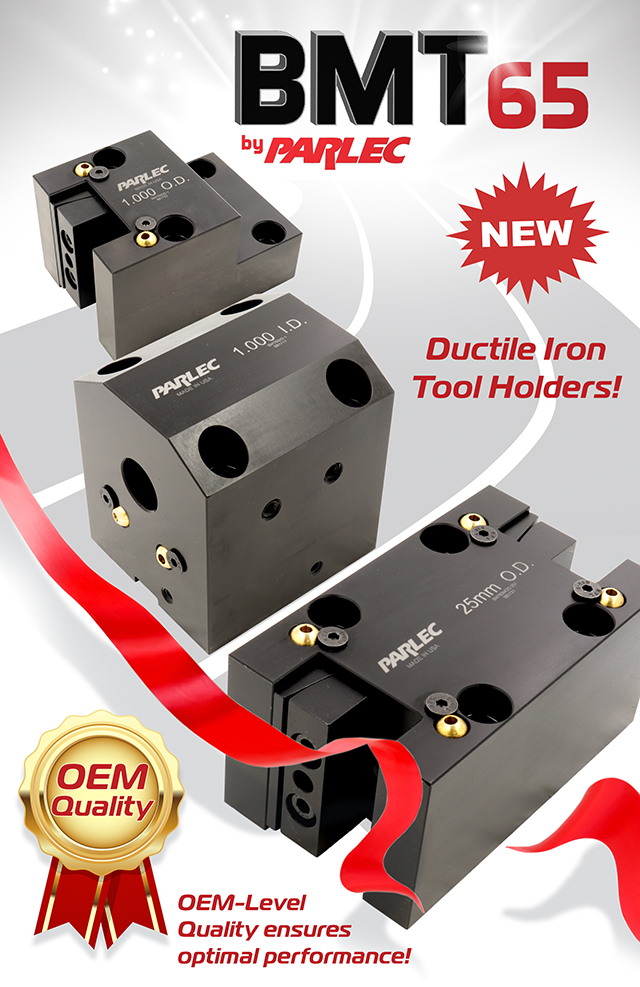
Parlec has been making BMT65 tool holders for one of the largest machine manufacturers in the world for many years. We have the know-how to produce top-quality BMT65 tooling to the most exacting standards. Parlec BMT65 holders match Haas BMT’s in design, dimensions, and material
Ductile Iron vs. Steel
Parlec BMT65 tool holders are made from ductile iron as opposed to steel that is used by many other providers. The largest machine OEM in the world requires ductile iron as opposed to steel. Ductile has superior shock absorption to steel – the average damping capacity for ductile iron is 6.6x higher than for SAE 1018 steel Ductile iron has a higher abrasion resistance due, in large part, to the high % of graphite that acts as a graphite lubricant
Coolant Delivery Hardware is Included
Adjustable coolant delivery ports are included on all Parlec BMT65 tool holders
Made-in-USA
Our American-made tooling is on-the-shelf and ready to go into production – today! No waiting on international shipping
BMT also provides:
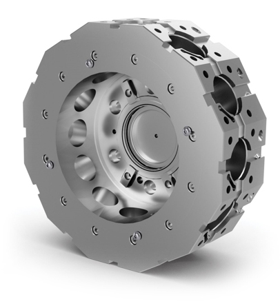
Wide surface mounting area provides extra-rigid connection to the turret to improve cutting performance and tool-life
This is especially important for driven tools that create high forces on the connection
Additional tool clearance when working with a tailstock – live tool drive is not right behind the turret
Easy installation without additional alignment as is required with BOT and VDI holders
Ability to run static and driven tools so parts may be completed in one setup
BMT65 Tool Holder Types
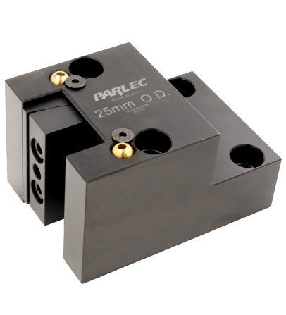
ID – Holds cylindrical tools to perform boring operations and/or other machining on the ID of the workpiece
OD – Holds stick tools to perform turning operations and/or other machining on the OD of the workpiece
Greg has been with Techniks Tool Group for over 23 years serving in many roles from VP of Sales to President & CEO during which he has gained a deep understanding of CNC manufacturing processes and how to optimize tooling and workholding solutions for specific applications. He has written several articles, white papers, and blogs on various tooling, deburring, and workholding-related topics. As a recognized subject matter expert on CNC tooling, Greg is often approached to provide opinions and content for technical articles.
It’s been estimated that a tool with a run-out of 50% of the tool’s chip load will reduce its tool-life by 40%.
That means that a 1/8” tool with a 0.00019” chip load per tooth will lose 40% of its tool-life with a run-out of less than 0.0001”.
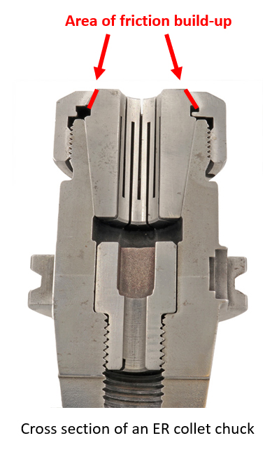
Excessive and inconsistent run-out from a properly setup ER collet chuck assembly typically occurs due to friction build-up between the 30° face of the collet and the collet nut.
As the collet nut presses down and turns against the 30° face of the collet, the collet face will tend to twist with the collet nut, distorting the shape of the collet. This radial distortion negatively affects tool run-out sine the collet bore is not longer straight.
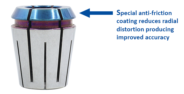
Parlec’s new P3 ER collets have a special anti-friction coating on the 30° face that dramatically reduces friction at this critical connection.
The result?
Improved tool runout
Longer tool-life
Less frequent tool changes
Improved surface finishes
Other Parlec P3 collet advantages:
3 micron T.I.R
Fewer slots that standard collets making them more rigid – in the cut!
Special slotting seal for coolant up to 2,000 PSI
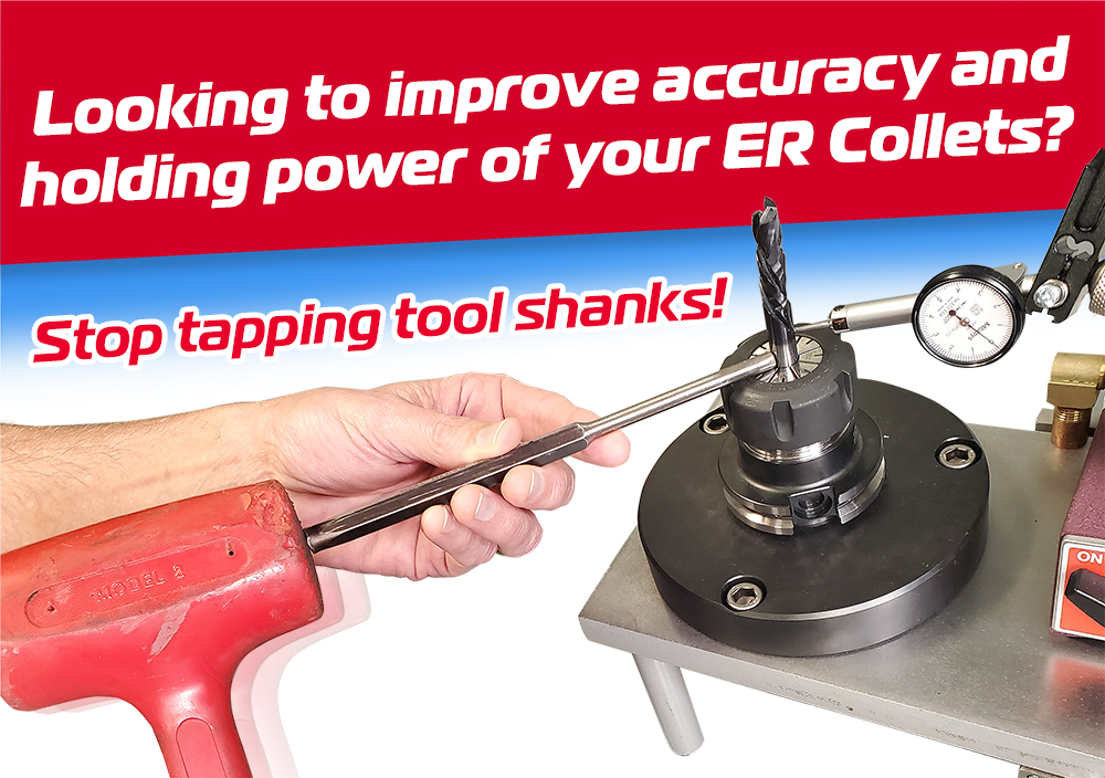
Don’t throw away you ER collet chucks to improve accuracy Try Parlec P3 collets and supercharge your ER collet system!
For help with your specific application, give the experts at Techniks Tool Group a call at (800) 803-8000 or email us at info@techniksusa.com.
Mike joined Techniks Tool Group in 2001 and launched the manufacturer’s representatives and distribution network for Techniks. Mike has served as VP of Sales since 2014 and managed the integration of Parlec’s sales and marketing teams into the Techniks Tool Group family. Mike’s extensive field experience has provided him a unique insight on manufacturing challenges and their solutions through optimized tool holding and work holding configurations across a broad range of industries.
The ER collet system is a tried-and-true tool holding system used by just about every machine shop. Customers like the ability to meet almost any job from drilling to milling to tapping and the flexibility to hold a variety of shank diameters by just changing the bore size of the collet. However, achieving optimal clamping pressure and repeatable accuracy are challenges that have resulted in some “creative solutions”. We’ve seen it all. From cheater bars to provide additional torque on the collet nuts to tapping tool shanks for better accuracy.
In this article we will dissect what’s going on with the ER collet system that creates these challenges and why these “creative solutions” actually work against improving holding power and accuracy. Finally, we will explore the unique solutions Techniks Tool Group has develop to counter the shortcomings of ER collet system including the revolutionary new Parlec P3 collets.
Setup Time
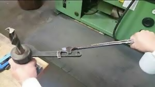
We’ve all seen it. It’s time to setup an ER collet chuck and out comes the cheater bar to tighten the collet nut. Why do shops feel the need to use cheater bars to adequately tighten collet nuts? Well, no one wants to under tighten a collet nut for fear of the cutting tool coming loose during operation potentially requiring re-work, producing scrap, or worse, creating a serious safety issue. But, as we shall see, cheater bars can actually negatively affect clamping pressure and accuracy.
Cheater Bars: Who Needs Them? NOBODY!
Cheater bars are an attempt to overcome one of the largest challenges of the ER collet system – friction. Friction robs the ER collet system of clamping pressure and can create inconsistent run-out of the cutting tool. Friction occurs between all mating surfaces of the ER tool holder assembly, most notably between the threads of the collet nut and the tool holder and between the collet nut and the 30° face of the collet.
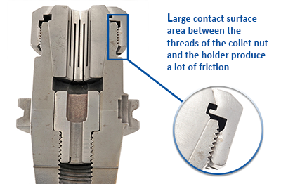
Let’s first look at the friction between the threads of the collet nut and the tool holder. The threaded areas of the collet nut and the tool holder create a lot of contact surface area. As a collet nut is tightened on the tool holder the ground threads of the nut and the ground threads of the tool holder produce a great amount of friction.
When using a torque wrench, the buildup of friction between the threads will cause the torque wrench to indicate the proper torque value has been achieved. However, the actual torque being transferred to the cutting tool shank in the form of clamping pressure may be far less than anticipated or required for optimal holding power.
To see a demonstration of how the friction robs the ER collet chuck assembly of holding power, click here.
Torque Wrenches – The First Line of Defense
Shops have been using the extra leverage cheater bars provide to overcome the friction buildup between the nut and holder threads in order to increase the clamping pressure on the cutting tool. However, there is no control over how much torque is actually being produced. Without control, there can be no consistency.
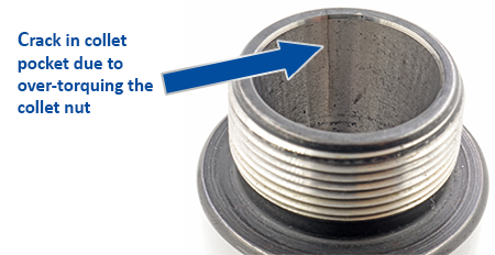
In fact, cheater bars often result in too much torque that can create a host of issues like cracked collet pockets in the holders, cracked collets, and inconsistent run-out.
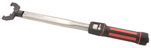
The first line of defense to ensure proper torque and setup of an ER collet chuck is a torque wrench. Torque wrenches are the “great equalizers”. Everyone, regardless of strength or size, can achieve the same torque on the collet nut with repeatable results. Shops looking to improve consistency should throw away their cheater bars and incorporate torque wrenches in their ER tooling setup.
Back to the Threads
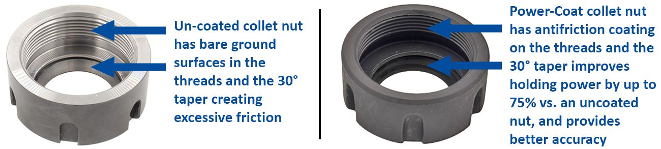
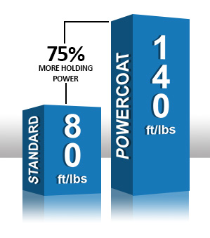
To overcome the challenges of friction buildup between the threads of the collet nut and the threads of the tool holder, Techniks Tool Group developed our exclusive “Power-Coat” collet nuts. Power-Coat collet nuts have a special anti-friction coating that drastically reduce the friction between the threaded connection as well as the at the 30° face of the collet.
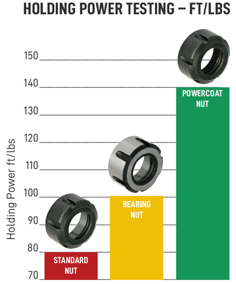
This permanent anti-friction coating helps Power-Coat ER collet nuts to achieve about 75% greater clamping pressure on the tool shank at the same torque specification as a standard, uncoated collet nut. No cheater bar required! Power-coat nuts come standard on all our Parlec and Techniks ER collet chucks.
To see a demonstration of the superior holding power of the Power-Coat nuts, click here.
Consistent Accuracy, The Elusive Goal
In addition to optimal clamping pressure, shops often struggle with achieving consistent accuracy from their ER tooling. It seems that one setup will produce good accuracy, while just loosening and retightening the collet nut will result in poor accuracy. To correct this, some operators tap the cutting tool shank until the desired accuracy is achieved. What’s going on?
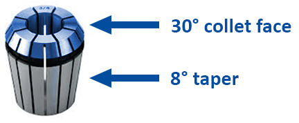
As the collet nut and collet assembly is being threaded onto the tool holder the collet will generally rotate with the collet nut. As the 8° taper of the collet mates with the collet pocket, it will stop rotating with the collet nut. You can rotate the nut back-and-forth and the collet will stay stationary.
However, the collet nut must be further tightened to achieve the proper torque specification. As the collet nut continues to rotate, friction builds-up between the now stationary 30° collet face and the collet nut. This friction twists the top of the collet, causing radial distortion.
Think of having your feet buried while someone is turning your shoulders. Eventually, your spine will twist and break. Ouch! This radial distortion produces uneven clamping pressure around the tool shank reduces clamping pressure and creates accuracy issues.
To correct for poor accuracy, some operators will tap the tool shank to bring it into the desired accuracy. However, just tapping the tool shank into tolerance does not solve for the uneven clamping pressure resulting from twisting the top of the collet. Once the machining starts, the tool shank will find its point of lowest energy and will, once again, move out of tolerance.
In order to achieve consistent accuracy, the friction between the 30° collet face and the collet nut must be reduced. Here, again, the Power-Coat collet nut helps overcome this challenge. Power-Coat collet nuts have the anti-friction coating on the mating surface with the 30° collet face. This greatly reduces the friction between the 30° collet face and the collet nut, so the radial distortion is reduced providing improved and consistent accuracy.
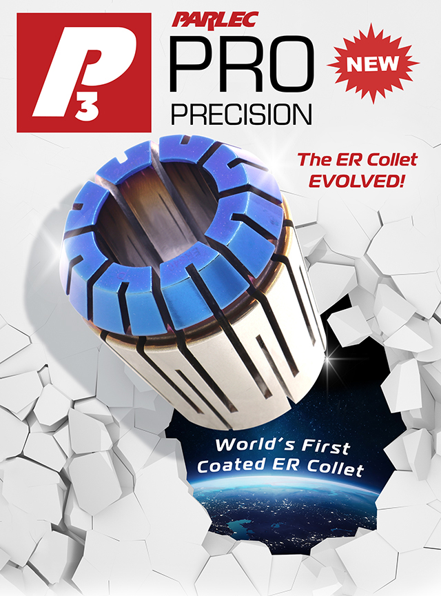
Introducing the P3 ER Collet System – The ER Collet System, EVOLVED!
To further improve the holding power and accuracy of the ER collet system, Techniks Tool Group has developed the world’s first coated ER collet system – the P3 ER collet system. P3 (Parlec Pro Precision) has a special anti-friction coating on the 30° collet face. This anti-friction coating enhances the results of the Power-Coat collet nuts to further reduce friction buildup between the 30° collet face and the collet nut reducing radial distortion. Also, P3 ER collets have a reduced number of slots making the collets more rigid and further reducing radial distortion.
The result? Improved clamping pressure on the tool shank and improved accuracy. No tapping required!
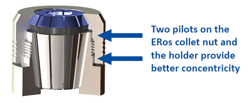
For Ultimate Accuracy, Go ERos!
For the ultimate in accuracy, Parlec offers the ERos ER system. ERos collet chucks (ERos = ER on-size) are proudly Made-in-the-USA and feature several design improvements that enhance the performance you can expect an ER tooling setup.
ERos chucks and nuts have two pilots to more concentrically align the nut on the holder further improving accuracy. ERos collet nuts do not have any slots, reducing wind vibration at high spindle speeds. Also, the ERos collet nuts have a concentric extraction ring to remove the collet from the holder creating a superior balanced assembly. While the ERos system will improve the performance of standard ER collets, when combined with P3 collets, the ERos system produces results that some of our customers say exceeds that of shrink fit or hydraulic chucks.
Shops considering other tooling technologies to improve consistent accuracy and holding power shouldn’t abandon their investment in ER collet chucks and give the Power-Coat collet nuts and P3 ER collet system a try. Want the ultimate in accuracy and holding power? Try out the ERos collet system and P3 collets.
These are just a few of the technologies Techniks Tool Group has developed to overcome some of the challenges of the ER collet system and achieve superior results.
For help with your specific application, give the experts at Techniks Tool Group a call at (800) 803-8000 or email us at info@techniksusa.com.
Greg has been with Techniks Tool Group for over 23 years serving in many roles from VP of Sales to President & CEO during which he has gained a deep understanding of CNC manufacturing processes and how to optimize tooling and workholding solutions for specific applications. He has written several articles, white papers, and blogs on various tooling, deburring, and workholding-related topics. As a recognized subject matter expert on CNC tooling, Greg is often approached to provide opinions and content for technical articles.
Machinists often are often challenged with the need to direct coolant to the cutting area. Getting coolant to the cutting area is critical for efficient chip evacuation, adding lubricity to the cutting surface, and cooling the cutting tool to avoid unnecessary heat build-up that can lead to premature failure. Flood coolant works well for surface cutting applications like face milling, but things are a bit more tricky when machining cavities or tapping as the workpiece can obstruct flood coolant. For these reasons, Techniks has developed a broad assortment of ER coolant collets to meet virtually any cutting application.
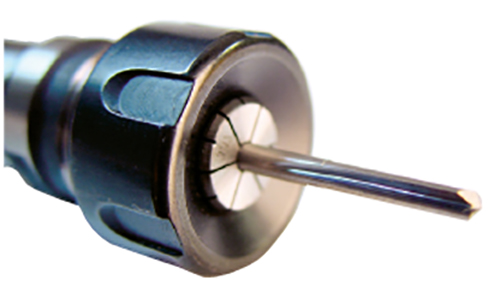
What is a Coolant Collet?
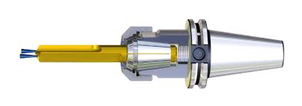
Coolant Collets get their name because they seal the cutting tool shank to direct coolant through the cutting tool. Coolant-through tooling is growing in popularity because of its effectiveness at clearing chips from the cutting area and permitting faster feeds and speeds. Coolant-through tools, such as end mills and drills, have coolant ports built into the tool shanks directing coolant at the cutting area, regardless of the depth of the hole or cavity. For proper performance and to avoid leaking and pressure loss, coolant collets are used to seal around the cutting tool shank prohibiting coolant from leaking through the slots in the collets and forcing the coolant through the cutting tool. This creates maximum coolant pressure at the cutting area which pushes chips away from the cutting path enhancing cutting performance and improving tool life.
What Options are Available for Coolant Collets?
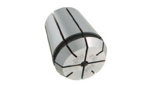
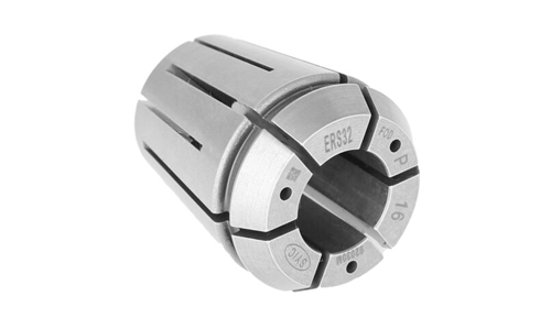
Steel Sealed Coolant Collet
Techniks offers several options for coolant collets. Our Steel-Sealed Coolant Collets have become a popular choice when using high-pressure coolant. Steel-Sealed Collets have a special slotting design that prevents coolant from reaching the collet face. Since the design of the slots prevent coolant leakage, these collets can be used in high-pressure coolant applications. Techniks Steel-Sealed Coolant Collets are pressure rated to 2,000 PSI. An important consideration for choosing the correct collet bore size is that Steel-Sealed Coolant Collets are intended for on-size use, meaning they are intended for use with a specific shank diameter.
Plug-Style Coolant Collet
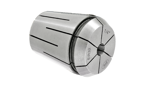
In addition to Steel-Sealed Coolant Collets, Techniks also offers plug-style coolant collets. Plug-style Coolant Collets, referred to as Coolant Collets, use rubber plugs in the slots to block coolant from leaking through the collet face. Most collet manufactures simply plug their standard collets in face slots to make coolant collets. Since standard ER collets have 16 slots (8 in the face and 8 in the back) these plugs can be rather small and can be blown out if coolant pressure exceeds their recommended value. In addition, the collapse range of standard collets, typically 0.040”, can cause plugs to be dislodged when used towards the bottom of the collapse range of the collet.
By contrast, Techniks Coolant Collets feature only 4 slots in the face. This permits larger plugs that can withstand higher coolant pressure more reliably. Techniks Coolant Collets are pressure rated to 750 PSI and have a 0.020” collapse range to avoid dislodging the plugs when clamping odd sized shanks.
What About Coolant-Through Taps?
ER Steel Sealed Rigid Tap Collet
Coolant-through taps are growing in popularity for the same reasons as coolant-through drills and end mills – they allow for superior chip evacuation. Tapping blind holes leaves very little room to evacuate chips. Therefore, coolant directed at the start of the tap help drive chips up the tap flutes and out the hole producing better thread quality and helping extend tap life.
To meet the growing need to machine with coolant-through taps, Techniks provides our ER Steel Sealed Rigid Tap Collets. These tap collets feature a unique slotting design that engages the square of the tap shank to positively lock the tap and also seal around the tap shank to direct coolant through the tap. Steel Sealed Rigid Tap Collets are available for inch and metric taps in ER16, 20, 25, 32, and 40 sizes.
ER Steel Sealed Collet with CoolBLAST Ports
What if My Tooling is Not Coolant-Through?
As good as coolant-through tooling is at helping direct coolant to the cutting area, there are instances when standard solid-shank tooling is the preferred option. For one, coolant-through tooling typically costs more than its solid-shank counterpart so changing to coolant-through tooling can be a costly endeavor. Also, very small tool shanks may not have the clearance to bore coolant ports, or a particular tool has already been spec’d into a job. For these instances Techniks offers our ER Steel Sealed Collets with CoolBLAST. CoolBLAST is a feature where coolant ports are drilled into the collet face. Coolant is sealed at the tool shank. The angled CoolBLAST ports direct the coolant to the cutting area. Steel Sealed Coolant Collets with CoolBLAST have a pressure rating of 1,400 PSI.
Don’t Forget the Collet Nut!
Coolant collets are generally more rigid and less collapsible than standard collets. Therefore, it is important to choose the right collet nut to ensure proper clamping pressure on the tool shank. Techniks PowerCOAT collet nuts feature an anti-friction coating that provides up to 75% greater clamping pressure than standard uncoated collet nuts. Uncoated collet nuts may not provide enough clamping power to ensure proper clamping pressure allowing the tool to slip while machining. Techniks PowerCOAT nuts are guaranteed to perform with our coolant collet options.
Which Coolant Collet System is Right for Your Application?
Give the experts at Techniks a call. Our knowledgeable team will help you select the coolant collet system that best meets your needs.
Greg has been with Techniks Tool Group for over 23 years serving in many roles from VP of Sales to President & CEO during which he has gained a deep understanding of CNC manufacturing processes and how to optimize tooling and workholding solutions for specific applications. He has written several articles, white papers, and blogs on various tooling, deburring, and workholding-related topics. As a recognized subject matter expert on CNC tooling, Greg is often approached to provide opinions and content for technical articles.
The combination of TTG and Eppinger offers our customers a convenient single source for the highest quality tooling solutions for CNC mills, lathes, and routers.
The combination of TTG and Eppinger offers our customers a convenient single source for the highest quality tooling solutions for CNC mills, lathes, and routers.
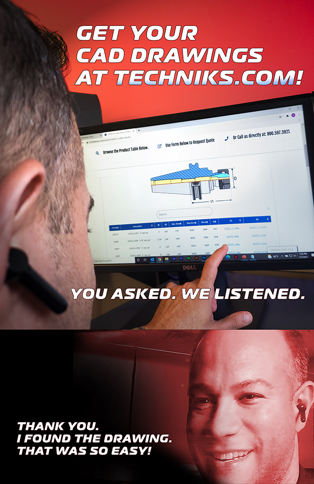
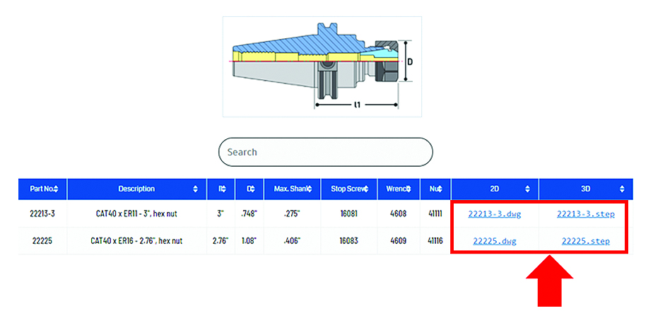
Techniks is excited to announce that we are entering into a new stage of development for our website. Over the past several weeks we have compiled 2D and 3D model files for each product available on Techniksusa.com.
That’s almost 4,800 total SKUs, 9,600 2D and 3D model drawings added for your convenience!
The addition of downloadable CAD files is just the next phase in our continued development of our site to improve its user-friendliness. You can now find your specific drawings through directly searching for the part number in the “Drawings” section of the main menu or by navigating directly to the product page. Simply navigate to the appropriate product table, locate the item you need, and click on the drawing file format you require. You will see a links to the 2D DWG and 3D STP files in the right-hand columns.
Can’t find what you’re looking for?
We are adding more drawings every day, but if you do not find the drawings you need let us know at info@techniksusa.com and we will prioritize your request to get you the drawings you need, FAST!
As you begin to take advantage of our available CAD files, please do not hesitate to continue to provide feedback on your website experience. It’s been with your help that Techniks is able to provide the highest levels of customer service.
Greg has been with Techniks Tool Group for over 23 years serving in many roles from VP of Sales to President & CEO during which he has gained a deep understanding of CNC manufacturing processes and how to optimize tooling and workholding solutions for specific applications. He has written several articles, white papers, and blogs on various tooling, deburring, and workholding-related topics. As a recognized subject matter expert on CNC tooling, Greg is often approached to provide opinions and content for technical articles.
The combination of TTG and Eppinger offers our customers a convenient single source for the highest quality tooling solutions for CNC mills, lathes, and routers.
The combination of TTG and Eppinger offers our customers a convenient single source for the highest quality tooling solutions for CNC mills, lathes, and routers.
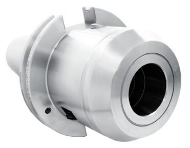
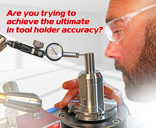
Triton Hydraulic Holders - Achieve the ultimate accuracy.
Triton Hydraulic Chucks deliver repeatable accuracy of <0.003mm to meet your most exacting tolerances.
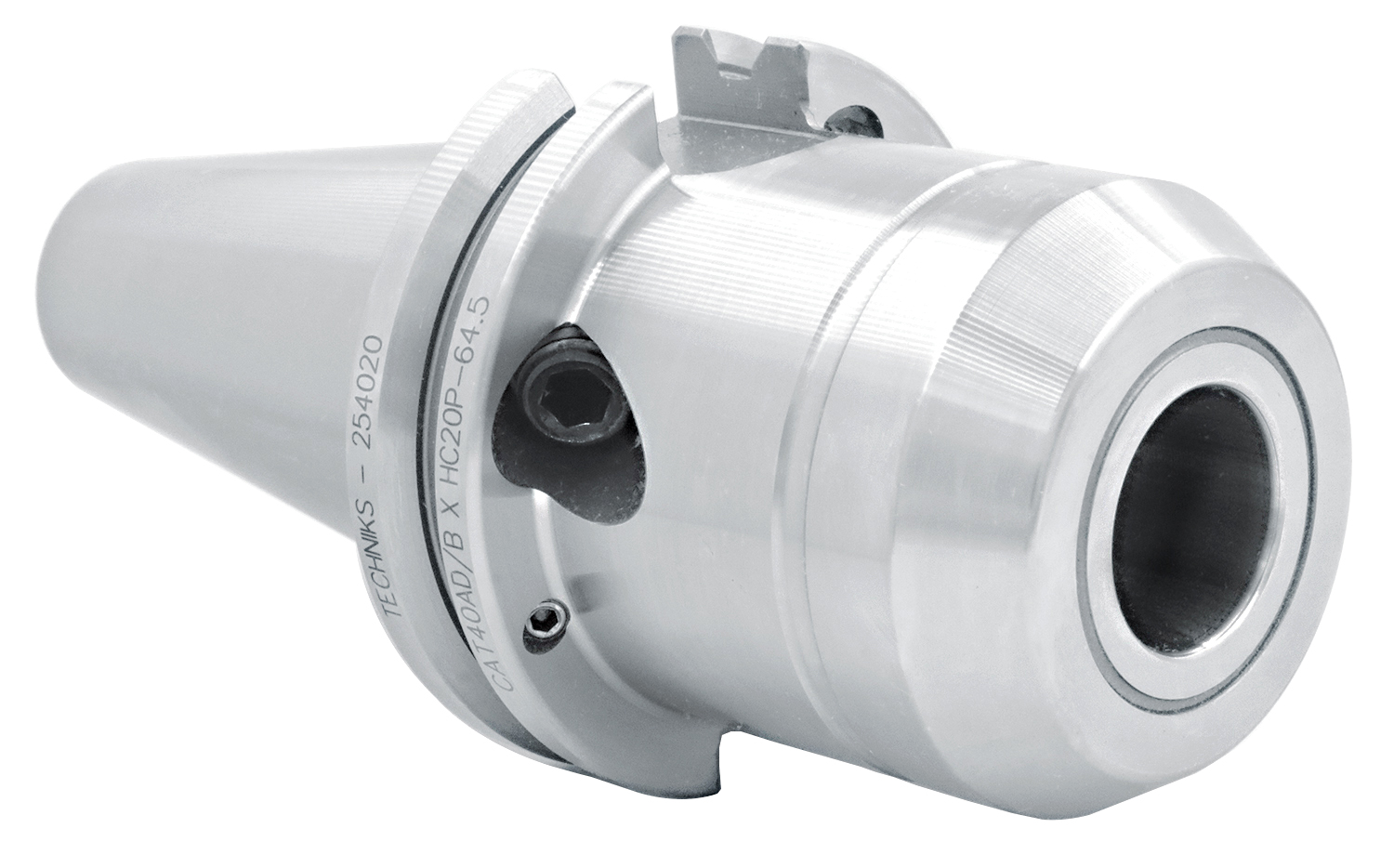
Triton hydraulic hydraulic chucks feature a thicker wall construction and more compact hydraulic design that concentrates the clamping force on the tool shank, increasing holding power up to 350% compared standard hydraulic chucks. The increased holding power enables Triton chucks to be used for heavy milling applications in addition to more typical operations like drilling, reaming, thread milling and finish milling.
Why Triton Hydraulic Holders
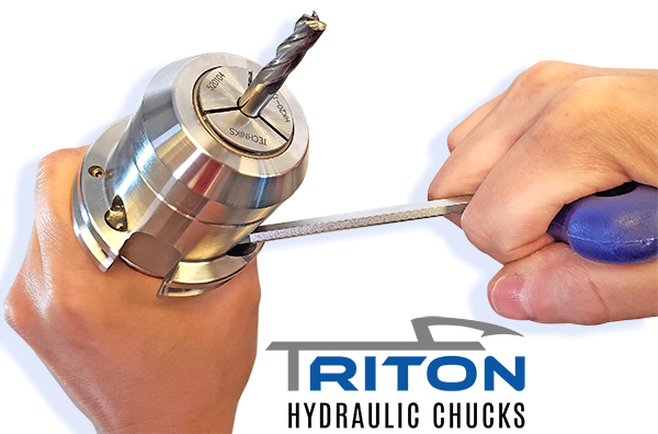
The hydraulic reservoir around the bore provides vibration-damping properties that reduce chatter in the cut, improving surface finish and enhancing tool life. Tool changes are performed with a hex wrench. Triton chucks have a repeatable accuracy of under 0.003 micron at 3×D and are balanced to a minimum of 25,000 rpm at 2.5 Gs for high-speed applications. CAT- and BT-tapered Triton chucks can provide through-spindle as well as AD+B flange coolant.
The chucks can hold shank diameters ranging from 1/8” to 1 1/4” by using reduction sleeves. We also offer reduction sleeves treated with its TTG-594 compound, that increase the holding power. Triton chucks are available in standard and dual-contact CAT 40/50, standard and dual-contact BT 30/40, and HSK 63A/100A.
Triton Hydraulic Chucks deliver repeatable accuracy of <0.003mm to meet your most exacting tolerances.
The Strength to Handle Your Toughest Applications
A redesigned hydraulic bladder delivers 3.5X the gripping force of standard hydraulic chucks and thicker bore walls provide greater stability in high material removal applications.
Flexible and Secure Reduction sleeves give you the flexibility to hold any shank diameter. Reduction sleeves with bores of ½” or 12mm and larger have been treated with TTG-594 to create H-LOCKED; the world’s strongest holding force in a reduction sleeve!
Quiet in the Cut Triton’s hydraulic bladder surrounds the tool shank and dampens vibrations, so tools run longer and quieter producing superior surface finishes and extending tool life.
Snappy Tool Changes Change tools with just a hex wrench; no tightening fixtures, no torque wrenches, no hassle!
Mike joined Techniks Tool Group in 2001 and launched the manufacturer’s representatives and distribution network for Techniks. Mike has served as VP of Sales since 2014 and managed the integration of Parlec’s sales and marketing teams into the Techniks Tool Group family. Mike’s extensive field experience has provided him a unique insight on manufacturing challenges and their solutions through optimized tool holding and work holding configurations across a broad range of industries.
The combination of TTG and Eppinger offers our customers a convenient single source for the highest quality tooling solutions for CNC mills, lathes, and routers.
The combination of TTG and Eppinger offers our customers a convenient single source for the highest quality tooling solutions for CNC mills, lathes, and routers.
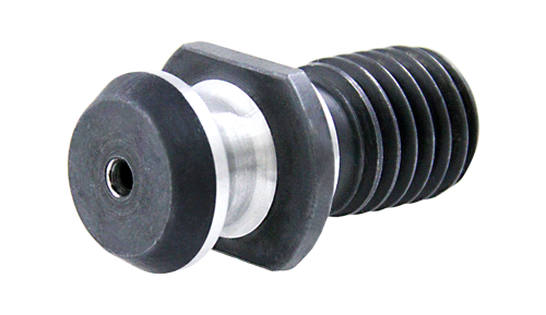
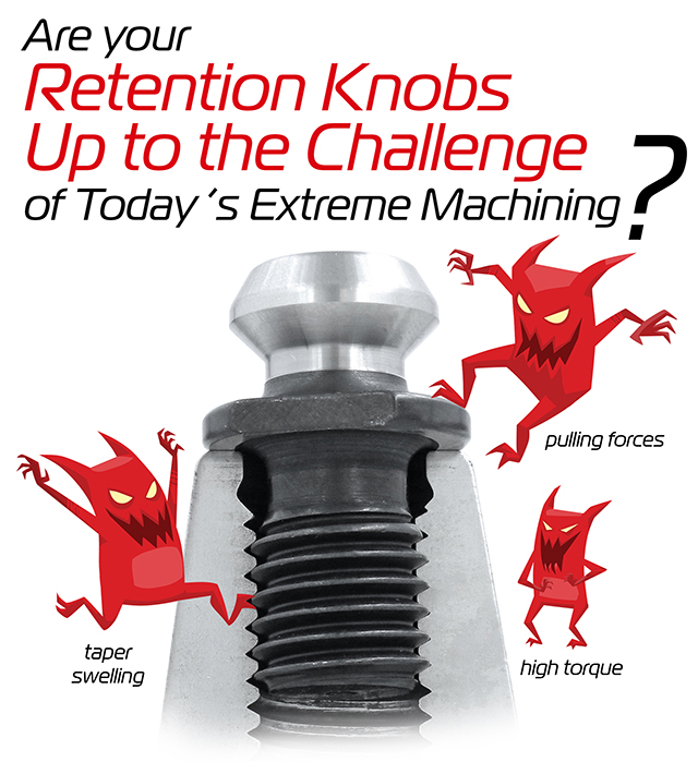
MegaFORCE Retention Knobs: For High-Torque Machining
Get the most secure hold with MegaFORCE Retention Knobs
Earlier this year we released our MegaFORCE High-Torque Retention Knobs, designed specifically for high-speed machining. Since then, we have been excited at some of the great feedback we have gotten on how it out-performs standard pull studs. When developing the MegaFORCE, we wanted to truly examine the issues that cause retention knob failure as speeds and feeds increase. The MegaFORCE has been designed specifically to resolve the issues that lead to imbalance and breakage. MegaFORCE Retention Knobs provide a more secure hold between spindle and holder, for longer tool life and better overall performance.
Why Retention Knobs Fail
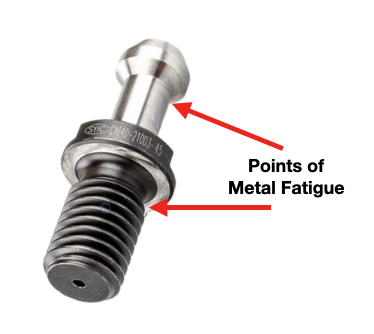
Pull studs encounter catastrophic failure as a result of metal fatigue caused by a number of reasons including: poor choice of base material, engineering design, machining process, poor heat treatment, and, sometimes, they have just met or exceeded their service life. Also, the repetitive loading and unloading cycles that the retention knob goes through is a significant source of stress that can cause fatigue and cracking at weak areas of the pull stud.
The most common failure points for a retention knob is at the top of the first thread, and the underside of the pull stud where the grippers or ball bearings of the drawbar engage and draw the toolholder into the spindle.
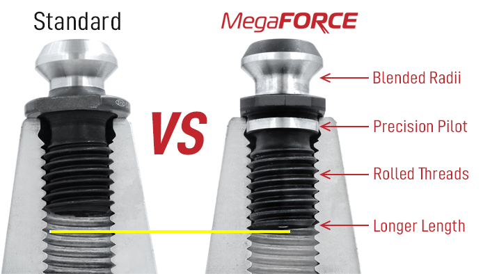
For the same reason we put corner radiuses on end mills, sharp corners are a common area of failure for any mechanical device. The same holds true with your pull studs: The sharp angles on the head of the retention knob and at the minor diameter of the threads are common locations of catastrophic material failure.
Remember, bigger Radii are stronger than sharp corners.
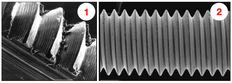
ROLLED THREADS VS. CUT THREADS
The first image shows how a cut thread has a higher coefficient of friction due the the cutting process. Image 2 shows how rolled thread has a lower coefficient of friction, which means that it engages deeper into the toolholder bore when subjected to the same torque. The cutting method tears at the thread material, creating small fractures, which become points of weakness and lead to tool failure. Rolled threads have burnished roots and crests that are smooth and absent of fractures common in cut threads.
Rolled threads produce a radiused root and crest of the thread and exhibit between a 40% and 300% increase in tensile strength over a cut thread. In the cold forming process, the thread rolls are pressed into the component, stressing the material beyond its yield point. This causes the component material to be deformed plastically, and thus, permanently. There are three rollers in the typical thread rolling head that maintain better concentricity by default than single point cutting of the threads.
Also, unlike thread cutting, the grain structure of the material is displaced not removed. Rolled threads produce grain flows that follow the contour of the threads making for a stronger thread at the pitch diameter which is the highest point of wear. The cold forming process also cold works the material which takes advantage of the nickel work hardening properties of 8620. By comparison, cut threads interrupt the grain flow creating weak points. The Techniks MegaFORCE retention knobs feature rolled threads that improve the strength of the knob by 40%.
Upgrade to MegaFORCE Retention Knobs
Ultimately, the only thing standing between a job well done and catastrophic failure is the retention knob. MegaFORCE Retention Knobs are designed to deliver superior performance and enhanced safety for the critical connection between your machine spindle and the tool holder. MegaFORCE Retention Knobs have been manufactured to increase the strength and durability of this critical connection.
Overall Length
MegaFORCE retention knobs feature a longer projection, for deeper thread engagement to prevent swelling. While a deeper thread engagement can help prevent taper swelling, applying proper torque to the retention knob always the best way to reduce taper swelling. An over-tightened retention knob may still cause taper swelling regardless of how deep it engages the threads of the tool holder.
Material
MegaFORCE retention knobs are made from 8620H. AISI 8620 is hardenable chromium, molybdenum, nickel low alloy steel often used for carburizing to develop a case-hardened part. This case-hardening will result in good wear characteristics. 8620 has high hardenability, no tempering brittleness, good weldability, little tendency to form a cold crack, good maintainability, and cold strain plasticity.
Blended Radii With the new MegaFORCE pull studs, stress risers of sharp angles have been eliminated through the blended radii on the neck where the gripper engages under the head of the pull stud.
Ground Pilot There is a ground pilot, underneath the flange, which provides greater stability. The pilot means the center line of the tool holder and pull stud are perfectly aligned.
Magnetic Particle Tested Each MegaFORCE retention knob is magnetic particle tested to ensure material integrity and physical soundness. MegaFORCE retention knobs are tested at 2.5X the pulling forces of the drawbar
Mike joined Techniks Tool Group in 2001 and launched the manufacturer’s representatives and distribution network for Techniks. Mike has served as VP of Sales since 2014 and managed the integration of Parlec’s sales and marketing teams into the Techniks Tool Group family. Mike’s extensive field experience has provided him a unique insight on manufacturing challenges and their solutions through optimized tool holding and work holding configurations across a broad range of industries.
The combination of TTG and Eppinger offers our customers a convenient single source for the highest quality tooling solutions for CNC mills, lathes, and routers.
The combination of TTG and Eppinger offers our customers a convenient single source for the highest quality tooling solutions for CNC mills, lathes, and routers.
MicroFLOAT Tapping system is the BEST CHOICE for getting the most life out of your taps
Transform tapping from frustrating to fantastic with MicoFLOAT!
Why is tapping so difficult?
Tapping is one of the most complex operations a CNC machining center performs. The tapping requires perfect synchronization between the machine’s feed-rate and the spindle rotation. The feed-rate must perfectly match the spindle rotation, so the feed-rate equals the thread pitch for each rotation of the spindle.
Machinists also find that tapping on a cnc prevents his ability to be actively engaged in the process and removes the ability to use his senses for guidance while the tap is in the hole. With a machining center, a machinist can’t stop in the middle of a tapping operation when something sounds or feels wrong. You know that something is incorrect only after a tap is broken or threads are bad.
It's all about the physics
To appreciate this concept, it’s important to understand that absent a specified spindle rotation and feed-rate, a tap will try to follow its thread pitch in terms of feed-rate. Why? It all has to do with Newton’s second law of thermodynamics, of course! For those of us that may have slept through high school physics, we might need a refresher course.
Basically, in the absence of external forces, any system will try to achieve a state of its lowest possible energy. Tapping threads takes energy. Following threads requires much less energy. Hence screwing a bolt into a threaded hole requires much less energy than tapping the threads. As the lead crests on a tap cuts the threads, the following crests will try to follow the existing threads, just like a bolt.
What can go wrong?
However, in the real world we need to consider the machine’s feed-rate and spindle rotation. If these two parameters are not perfectly synchronized, the result is unwanted forces on the tap that can produce less than optimal thread quality, cause premature thread wear, and/or result in broken taps. For example, if the feed-rate is less than the thread pitch for one rotation of the spindle, the tap will “drag”, or be pulled back, into threads it has already cut. This “drag” force engages the tap in cutting that would otherwise be used to simply cleanup the existing threads produced from the leading crests.
The same is true if the feed-rate is greater than the thread pitch for one rotation of the spindle. Here, the tap is pushed into the already cut threads. In both instances, thread quality is compromised, and the tap is subjected to forces that prematurely wear the tap and can result in breakage.
Further complicating matters is exiting the tap from the threaded hole. If the tap does not perfectly follow the existing thread out of the hole, the tap will engage in unwanted cutting, or re-threading, that degrades thread quality and causes unnecessary wear on the tap.
But my machine has rigid tapping, so I’m OK, right?
Not so fast. Rigid tapping on CNC machines promised to perfectly match the feed-rate with the spindle rotation to eliminate these issues. However, the reality is that, while helping to provide some synchronization between the feed-rate and the spindle rotation, rigid tapping is not able to achieve perfect synchronization. This is very apparent as the tap reaches the bottom of its cycle and is reversed to exit the hole. Here, again, physics is to blame!
But my machine has rigid tapping, so I’m OK, right?
One of the main advantages of rigid tapping is depth control accuracy on blind holes. To do the job accurately and consistently, a holder is needed that has enough compensation to get good tap life without causing variations in depth control. Rigid tapping on CNC machines promised to perfectly match the feed-rate with the spindle rotation to eliminate these issues. However, the reality is that, while helping to provide some synchronization between the feed-rate and the spindle rotation, rigid tapping is not able to achieve perfect synchronization. This is very apparent as the tap reaches the bottom of its cycle and is reversed to exit the hole. Here, again, physics is to blame!
Physics strikes again!
In a perfect world, at the bottom of a tap cycle, the spindle rotation and feed-rate would instantaneously stop in perfect unison and then instantaneously reverse at the proper rotational speed and feed-rate. If this were the case, we would almost never break any taps. Enter physics.
Because the spindle has mass it is subject to Newton’s first law of thermodynamics. Most notably, inertia. Simply put, since the spindle is rather large and heavy it is not possible to instantaneously stop the spindle rotation and feed-rate in perfect unison. The spindle rotation and feed-rate must have time to decelerate before stopping. The same is true when starting to reverse the tapping cycle. The spindle rotation and feed-rate must have time to accelerate up to the desired parameters. Further complicating matters is that these two parameters are individually affected by inertia, meaning that perfect synchronization is not possible.
The result?
This imperfect synchronization between spindle rotation and feed-rate at the bottom the tapping cycle creates tremendous forces on the tap. This is why most taps break at the bottom of a tapping cycle. The loss of synchronization when reversing also affects the entire exit cycle since the entry and exit parameters are not perfectly matched. This creates higher forces on the tap during exit.
If a tap holder with tension-compression float is used, tap life and thread quality can be dramatically improved, because these extra axial forces on the tap are eliminated. The problem with traditional tension-compression holders is that they can cause large variations in tapping depth. As a tap becomes dull, the pressure needed to start the tap into the hole increases, and more compression stroke within the tap driver is used before the tap starts to cut. The result is a shallower tapping depth
MicroFLOAT to the rescue!
To counter the inevitable inability to perfectly synchronize the feed-rate and spindle rotation, especially at the bottom of a tapping cycle, Techniks offers the MicroFLOAT tapping system. The MicroFLOAT system provides compensation so these synchronization errors are smoothed out and do not put unnecessary forces on the tap to improve thread quality, extend tap life, and cause less tap breakage.
How does MicroFLOAT work?
When starting a tap, it is helpful to have a relatively rigid assembly. This helps get the tap started in the hole and begin cutting threads. If the tapping system allows too much “push float”, or compression, when entering the hole, the tap will spin-out creating a mess of the threads at the top of the hole. Some compression is helpful since when the tap enters the hole forces try to push the tap out of the hole and slow the spindle rotation (physics, again!). A little compression allows these forces to do their work, while providing time for the feed-rate and spindle rotation to catch back up and get in lock step with each other. The MicroFLOAT system offers 0.008” of compression to help get taps started, but not enough to allow the tap to spin before it starts cutting threads.
Even though the discrepancy between the machine synchronization and the tap pitch is very small, the forces exerted on the tap with a solid holder are high. Measuring the thrust forces shows that a solid holder can exert 84 times greater axial forces on the tap than when using a microfloat tap holder doing exactly the same rigid tapping operation.
At the bottom of a tapping cycle, the MicroFLOAT system provides 0.040” of tension or “pull float”. As described earlier, the spindle rotation and feed-rate cannot stop and reverse to the necessary rates instantaneously. The MicroFLOAT system provides enough tension to allow time for the spindle rotation and feed-rate to decelerate, reverse, and accelerate to the required parameters on the way out. This mitigates the forces on the tap at the bottom and though the exit of the tapping cycle and results in improved thread quality, extended thread life, and fewer broken taps.
Greg has been with Techniks Tool Group for over 23 years serving in many roles from VP of Sales to President & CEO during which he has gained a deep understanding of CNC manufacturing processes and how to optimize tooling and workholding solutions for specific applications. He has written several articles, white papers, and blogs on various tooling, deburring, and workholding-related topics. As a recognized subject matter expert on CNC tooling, Greg is often approached to provide opinions and content for technical articles.
The combination of TTG and Eppinger offers our customers a convenient single source for the highest quality tooling solutions for CNC mills, lathes, and routers.
The combination of TTG and Eppinger offers our customers a convenient single source for the highest quality tooling solutions for CNC mills, lathes, and routers.
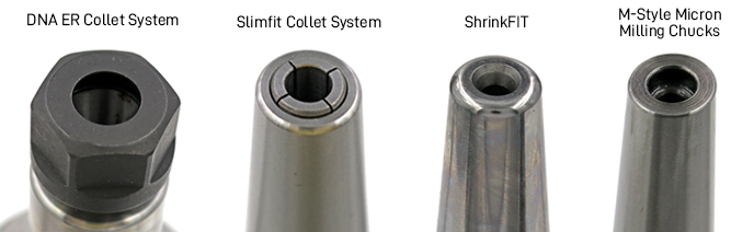
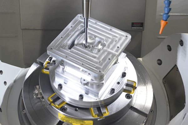
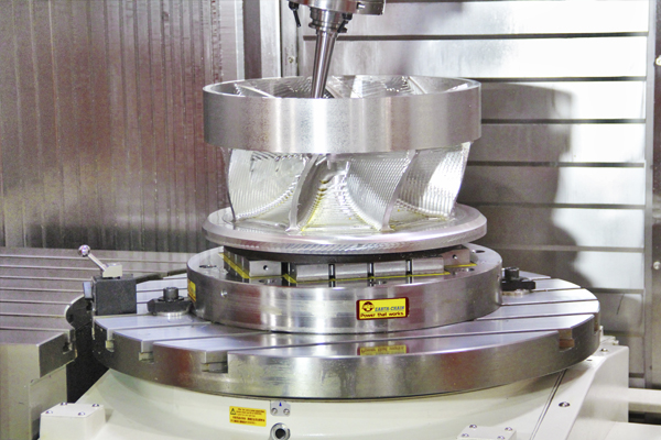
Tooling Solutions for Narrow and Deep Cavity Milling
Check out our narrow-nosed and slimfit collet systems.
Milling in tight corners or deep cavities present machinists with a lot of different tooling requirements and machining parameters to consider. According to this article from cnccookbook.com, the first step is simply addressing the common challenges of deep pocket milling; including tool deflection, which can lead to excessive machine chatter, wall taper, poor wall finish, and generally poor tool life and part quality.
Deep Pocket machining will almost always require multiple stepdown passes to reach the bottom of the cavity. The worse the tool deflection issues, the more passes will be required. It’s advised to focus on limiting the stickout, or projection, of the cutting tool from the holder as much as possible. We are speaking in the context of extended lengths, so this is relative to your part’s operation and desired wall depth.
“In cases where you have flutes the full length of the tool, they’re going to be rubbing and potentially cutting the walls created by previous passes. That needs to be minimized, and the right way to do that is to use tool shanks that have been relieved so they don’t contact the wall.”
While multiple stepdown passes are inevitable, machining parts with high walls require extended reach holders and end mills in order to mill at your required depths. Once your tooling is configured to reach your desired depth, we want to limit witness marks as much as possible, with each pass, in order to achieve the highest quality part. Techniks Extended length tools and SlimFIT holders provide the reach you need to get into the tightest spaces, combined with high quality, precision cutting tools, you can finally improve your deep pocket machining.
1) DNA ER Collet System
DNA collets provide shorter projection from the collet chuck for better rigidity and when clearance is needed. The DNA collet and nut system provides better rigidity and are more accurate than ER for small diameter shanks.
SlimFIT collets are longer overall than ER collets and feature a 4˚ taper, delivering better engagement between collet and tool shank, resulting in better accuracy and balance than ER systems.
If you do high speed, or high torque machining you should seriously consider the benefits of shrink fit technology. Shrink fit uses the expansion and contraction properties of metal to provide extremely powerful tool holding.
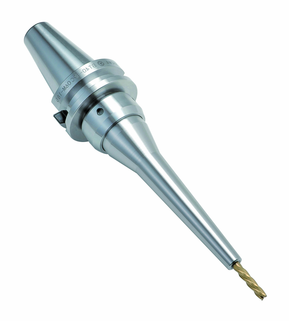
The M-style mold chuck’s narrow-nose design allows for deep, hard-to-reach machining; perfect for cutting deep die molds and any application where reach and clearance demand enhanced precision and performance.
Greg has been with Techniks Tool Group for over 23 years serving in many roles from VP of Sales to President & CEO during which he has gained a deep understanding of CNC manufacturing processes and how to optimize tooling and workholding solutions for specific applications. He has written several articles, white papers, and blogs on various tooling, deburring, and workholding-related topics. As a recognized subject matter expert on CNC tooling, Greg is often approached to provide opinions and content for technical articles.
The combination of TTG and Eppinger offers our customers a convenient single source for the highest quality tooling solutions for CNC mills, lathes, and routers.
The combination of TTG and Eppinger offers our customers a convenient single source for the highest quality tooling solutions for CNC mills, lathes, and routers.
Step 2) To join the chat simply login to your google/gmail account.
We are excited to join the team at Flex Machine Tools for an episode of their FlexLive YouTube series of high-quality live CNC machine demonstrations. Their talented hosts will guide you through some of the latest additions to our Techniks and Parlec brands. Our friends at Robbjack Carbide Cutting Tools have been kind enough to let us combine their high-precision cutting tools with our holders to show how TTG can help you improve your CNC production.
On-hand during the event will be our very own VP of Sales, Mike Eneix, and Midwest Sales Manager, Brian Haskett, to provide technical background of these new technologies. Also joining the discussion will be VP of Engineering for Robbjack, Mike MacArthur, to add his 20 years of experience to the show and explain how combining high-precision cutting tools with Techniks Certified Holders can improve your overall production.
The show will cover a detailed overview of our latest ShrinkFIT solutions, demonstrating our compact, but powerful, 00450 ShrinkFIT Machine; as well as run through of our line of ShrinkFIT holders, including coolant-ported, SlimPRO, SFS modular system, and heavy wall shrinkfit holders.
Also, for the first time, the superior cutting performance of our Triton Hydraulic Holders will be live and in action. With its enhanced hydraulic bladder, Triton hydraulic holders are disproving the theory that hydros are reserved for just light milling operations. You will see how our Triton chucks are built to hog!
Our final demonstration will feature our Parlec brand Micron Milling Chucks. We will describe how the unique features of Micron chucks help improve tool life, surface finish, dimensional accuracy and productivity for all types of heavy duty applications. The M-style Micron Mold Chucks are perfect for extended lengths and tight spaces.
We can’t wait to deliver an engaging and informative event, and we are excited to have the chance to interact with other machinists and watch chips fly! If you make the live event, simply login to your google/gmail account and will will be able to join the discussion, and ask any of our experts any questions you may have. But, if you don’t happen to make the live event, you will be able to stream the show in its entirety from YouTube anytime.
This website uses cookies to improve your experience. We'll assume you're ok with this, but you can opt-out if you wish. Cookie settingsACCEPT
Privacy & Cookies Policy
Privacy Overview
This website uses cookies to improve your experience while you navigate through the website. Out of these cookies, the cookies that are categorized as necessary are stored on your browser as they are as essential for the working of basic functionalities of the website. We also use third-party cookies that help us analyze and understand how you use this website. These cookies will be stored in your browser only with your consent. You also have the option to opt-out of these cookies. But opting out of some of these cookies may have an effect on your browsing experience.
Necessary cookies are absolutely essential for the website to function properly. This category only includes cookies that ensures basic functionalities and security features of the website. These cookies do not store any personal information.
Any cookies that may not be particularly necessary for the website to function and is used specifically to collect user personal data via analytics, ads, other embedded contents are termed as non-necessary cookies. It is mandatory to procure user consent prior to running these cookies on your website.
Functional cookies help to perform certain functionalities like sharing the content of the website on social media platforms, collect feedbacks, and other third-party features.
Performance cookies are used to understand and analyze the key performance indexes of the website which helps in delivering a better user experience for the visitors.
Analytical cookies are used to understand how visitors interact with the website. These cookies help provide information on metrics the number of visitors, bounce rate, traffic source, etc.
Advertisement cookies are used to provide visitors with relevant ads and marketing campaigns. These cookies track visitors across websites and collect information to provide customized ads.


 Pull studs encounter catastrophic failure as a result of